Perform a contact resolution
Targeted SesamX version: V2022_03
Introduction
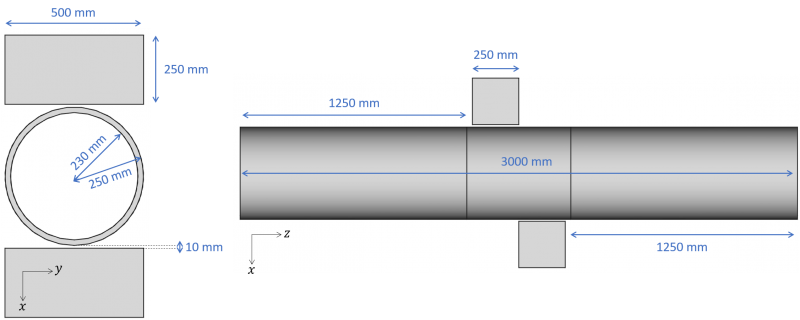
This how-to showcases how to perform a contact resolution on a SesamX model. As an illustration, we will work on a pipe crushing model. We will detail how to prepare the model in order to define the contact conditions, and how to set up the non linear resolution scenario. You can find all the relevant data used to write this how-to at the end of this page. The following figures give an illustration of the pipe crushing model used, as well as its relevant dimensions.
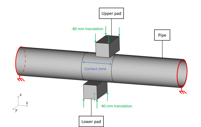
For the resolution scenario, we will consider the pipe clamped on its ends. And the pads will translate symmetrically along the $x$ axis by 80 $mm$. The pads will enter into contact with the pipe and they will start deforming the pipe.
The pipe is made of aluminum with the following properties:
- Young's modulus: $E = 70 GPa$
- Poisson's ratio: $\nu = 0.33$
And the pads are made of steel with the following properties:
- Young's modulus: $E = 200 GPa$
- Poisson's ratio: $\nu = 0.3$
We assume that there is no plastic deformation during the simulation. Even though this is not realistic, this simulation is still interesting to understand how to properly set up contact conditions on a model.
Model preparation
In order to set up a contact simulation, the first step is to prepare the mesh to support the contact definition. We will consider the following mesh as a starting point.
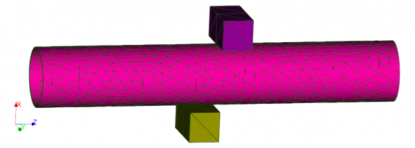
The pipe is made of quadratic tetrahedron elements while the pads are made of linear tetrahedron elements.
There are 2 contact zones to define on our model: one between the upper pad and the pipe, and the other between the lower pad and the pipe.
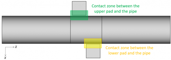
We will use the node-to-surface contact condition to modelize the contact zones. As discussed in the CREATE-CONTACT function, it is wise to choose the pads as the master sides, and the pipe as the slave side. Indeed the pads faces are flat and their mesh is coarser than the pipe mesh. However, for this how-to we would like to define symmetric contact conditions between the pipe and the pads. Hence we also need to define the pipe as the master side and the pads as the slave sides.
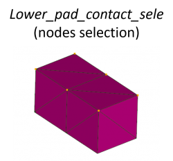
To be able to define the pads faces as a master side, we need 2D coating elements on these faces. And we need to make sure that theses 2D elements normals point outward. Then to prepare the master side for each pad, we simply need to create one selection per pad composed of the 2D elements.
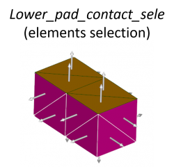
To prepare the slave side for the pads, we need to create one selection per pad composed of the nodes that should not penetrate the pipe.
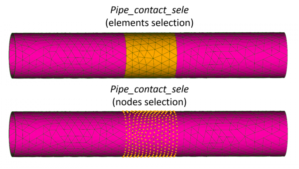
Similarly, to prepare the master side on the pipe we need a selection of the 2D coating elements. And to prepare the slave side on the pipe we need a selection of the nodes that should not penetrate the pads.
Contact definitions
To define the contact conditions we use the CREATE-CONTACT function. Although there are 2 contact zones in our model, we are going to define 4 NTS-ZONE in the contact case: each true contact zone is doubled in order to symmetries the contact definition (slave and master sides are switched as explained above). Hence, we define the following NTS-ZONES:
- Master = upper pad, Slave = pipe, with a tolerance of 300 $mm$,
- Master = pipe, Slave = upper pad, with a tolerance of 100 $mm$.
- Master = lower pad, Slave = pipe, with a tolerance of 300 $mm$.
- Master = pipe, Slave = pipe, with a tolerance of 100 $mm$.
The 300 $mm$ tolerance makes sure that the pipe nodes capture the pads nodes when the pipe come close to the pads. When the pipe is the master side, we can use a smaller tolerance because the pipe mesh size is smaller than the pads mesh size.
To summarize, the contact definition is provided by the following SesamX command:
CREATE-CONTACT
  NAME: CONTACT_CASE
  MODEL: PIPE_CRUSHING
  NTS-ZONE
    TOLERANCE: 300.
    ON-NODES-FROM: Pipe_contact_sele
    ON-ELEMENTS-FROM: Upper_pad_contact_sele
  NTS-ZONE
    TOLERANCE: 100.
    ON-NODES-FROM: Upper_pad_contact_sele
    ON-ELEMENTS-FROM: Pipe_contact_sele
  NTS-ZONE
    TOLERANCE: 300.
    ON-NODES-FROM: Pipe_contact_sele
    ON-ELEMENTS-FROM: Lower_pad_contact_sele
  NTS-ZONE
    TOLERANCE: 100.
    ON-NODES-FROM: Lower_pad_contact_sele
    ON-ELEMENTS-FROM: Pipe_contact_sele
Resolution scenario
We define first the constraint case holding the boundary condition on the pipe ends using the CREATE-CONSTRAINT function:
CREATE-CONSTRAINT
  MODEL: PIPE_CRUSHING
  NAME: PIPE_CONST_CASE
  DISPLACEMENT-SPC
    TX: 0.
    TY: 0.
    TZ: 0.
    RX: 0.
    RY: 0.
    RZ: 0.
    ON-NODES-FROM: Pipe_bound_sele
And then we define the constraint case imposing the pads vertical displacement (again using the CREATE-CONSTRAINT function):
CREATE-CONSTRAINT
  MODEL: PIPE_CRUSHING
  NAME: PADS_CONST_CASE
  DISPLACEMENT-SPC
    TX: 80.
    TY: 0.
    TZ: 0.
    RX: 0.
    RY: 0.
    RZ: 0.
    ON-NODES-FROM: Lower_pad_disp_sele
  DISPLACEMENT-SPC
    TX: -80.
    TY: 0.
    TZ: 0.
    RX: 0.
    RY: 0.
    RZ: 0.
    ON-NODES-FROM: Upper_pad_disp_sele
Finally, in order to compute the response of the model, we define a non-linear static resolution scenario using the SOLVE function:
SOLVE
  NAME: NL_ANALYSIS
  MODEL: PIPE_CRUSHING
  GEOM-NL: YES

  STEPS
    STATIC-STRESS
      NAME: LOADING
      NB-LEVELS: 10
      CVG-CRITERIA
        MAX-FORCE: 1.
        MAX-MOMENT: 1.
        MAX-TRANSLATION: 1.
        MAX-ROTATION: 1.
        MAX-CONTACT-PENETRATION: 1.
      CONSTRAINTS
        - NAME: PIPE_CONST_CASE  AMPLITUDE-FUNCTION: "1"
        - NAME: PADS_CONST_CASE  AMPLITUDE-FUNCTION: "t"
      CONTACT: CONTACT_CASE
The contact precision is set to 1 $mm$. This means that SesamX tolerates a contact penetration of at most 1 $mm$. And the resolution is split among 11 levels in order to apply the pad translation incrementally (from 0 $mm$ to 80 $mm$).
Simulation results
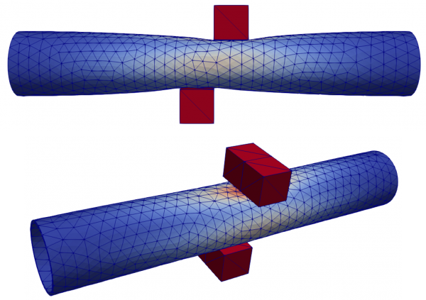
The following figure depicts the deformation of the model at the last computed level (associated with 80 $mm$ pads translation). As expected, the pads enter into contact with the pipe and deform it. While zooming into the contact area we can see that the pads nodes do not penetrate (at worst up to 1 $mm$) the pipe elements and vice versa.