3.5.13. CREATE-CONTACT function
optional
This function is used to define contact conditions on the model.
A contact condition consists of a non penetrability constraint between 2 geometrical entities of the model. For instance, 2 parts that cannot penetrate each other. To define a contact condition, you need to specify the contact zone (the geometries that cannot penetrate), then the contact orientation, and finally the contact parameters (telling SesamX how to behave).
Concepts introduction
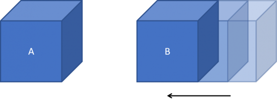
Let's suppose we have 2 parts (A and B) facing each other. And during our simulation, part B is moving to the left and gets closer to part A. We would like to modelize that, at some point, part A and B will enter into contact.
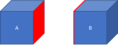
In this example, the contact zone is made of the 2 faces belonging respectively to part A and B (shown in red in the image). This is where the contact is to take place.
Given these 2 surfaces, to tell if there is a contact, we must also provide the contact orientation. This orientation is depicted as a normal vector attached to one side of the contact zone. For our example, let's suppose the normal is attached to the side A. For 2 points $ P_A $ on side A, and $ P_B $ on side B, we say that the contact is closed when $ \underline{P_A P_B} \cdot \underline{n} \le 0 $ (part A and B are indeed in contact). Otherwise, we say that the contact is open.
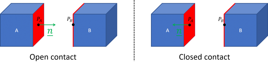
During the resolution, a contact force will be introduce only when the contact is closed.
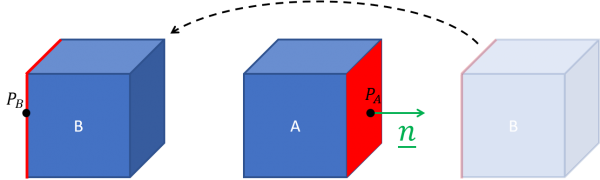
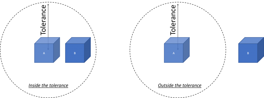
However, up to this point, the contact condition definition is not robust. Indeed, it does not embed any proximity criteria between the 2 sides of the zone. For instance, if part B jumps over part A and ends up in the following configuration, it is wrong to consider that there is a contact.
To circumvent this issue, we can use a tolerance parameter during the resolution. A potential contact is considered only when the 2 sides of the contact zone come closer than the tolerance.
This is all that has to be known to properly define contact conditions in SesamX.
How to define contacts in SesamX
From the previous explanations, we can derive the SesamX implementation of the contact condition.
Mesh and selection preparation
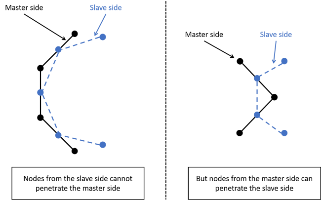
Currently, SesamX enables you to define only node-to-surface (NTS) contact zones. This type of contact zone is non symmetric: one side of the zone is made of element faces (known as the master side), while the other side is made of nodes (known as the slave side). This contact zone modelization is such that the nodes from the slave side cannot penetrate the faces from the master side. But the nodes from the master side can penetrate the slave side. The following picture showcases this behavior. For convenience reasons, the contact orientation is not shown. But it is such that the slave side cannot penetrate the master side from right to left.
Furthermore, SesamX considers that the contact orientation is carried by the master side of the contact zone.
To be able to define a NTS zone, you first need to prepare your mesh. Indeed, the faces composing the master side of the zone are in fact 2D elements. And you must also pay attention to the elements normal (that you can control by switching the connectivity order for manually defined element, or directly in your meshing software). You can create 2D elements with the sole aim to use them in contact definitions, you do not need to apply any property on these elements. SesamX considers these elements as “dummy elements” and they will work fine if used in contact definitions. On the other hand the slave side of the zone is composed of nodes only. Let's illustrate our previous example with a real mesh.
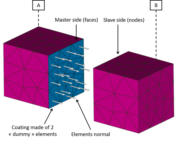
Then SesamX expects you to provide the master side selection (composed of the master 2D elements) through the ON-ELEMENTS-FROM keyword, and the slave side selection (composed of the slave nodes) through the ON-NODES-FROM keyword.
Contact detection
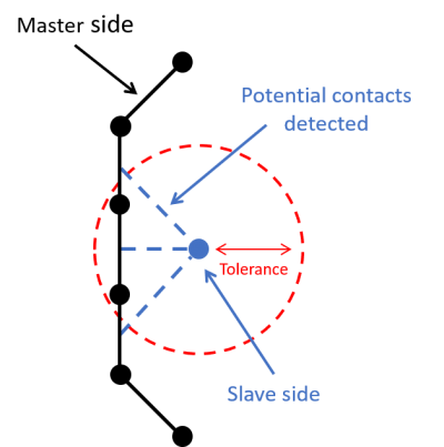
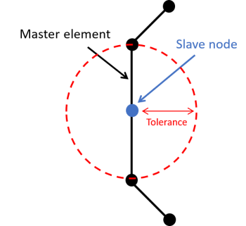
The TOLERANCE parameter drives how SesamX detects potential contacts. During the resolution, for each slave node SesamX will seek for the master nodes whose distance to the slave node is smaller than the tolerance. Such master nodes are qualified as captured master nodes. SesamX will then consider a potential contact between the slave node and each face connected to the captured master nodes, as showcased in the following picture.
Contact between quadratic meshes
Applying node-to-surface contacts between quadratic meshes can lead to poor simulation convergence. Everything works fine when the master side is composed of quadratic elements. However issues may arise when the slave side is composed of intermediate nodes belonging to quadratic elements. To avoid this pitfall, SesamX automatically delete intermediate nodes (coming from quadratic elements) from the slave side selection. This solution enables a better simulation convergence. But it is not perfect because there can be contact violations on these intermediate nodes. Nevertheless, if these contact violations are too severe, you can reduce them while refining the mesh on the slave side.
How to choose which side is the slave and which side is the master
You will often face the dilemma of choosing which side is the master and which side is the slave. Hence, the following advices aim to facilitate your choice.
When one side of the contact zone is more rigid than the other side:
- If this side is flat, then it should be the master side.
- If this side is not flat but less dense in nodes than the other side, then it should also be the master side.
- Else it should be the slave side.
When the 2 sides of the contact zone are of equal rigidity, the side that is the less dense in nodes should be the master side.
The previous advices are guidelines that may not work in every situation. In such complicated situations, you can “symmetrize” the contact condition by superimposing 2 NTS contact zones where the slave and master are switched.
Whatever the choice you make, you should always check that during the simulation, the 2 sides of the contact zone do not penetrate each other.
How to choose the tolerance parameter
Choosing the value of the tolerance is not an easy task. Mathematically, the tolerance should not be less than half the size of the smallest master element edge or diagonal (as showcased in the following figure). Otherwise the slave node could be at the center of the master element without any potential contact detected. In practice, we advise to keep the tolerance parameter above 3 times the size of the smallest master element edge or diagonal.
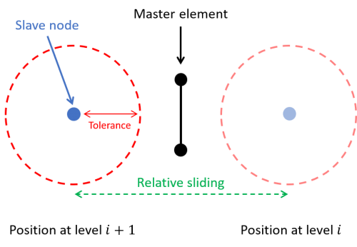
There is no mathematical upper bound. If you choose a very large tolerance value, SesamX will detect every possible contact that may arise during the resolution. This will lead to a performance drop but the resolution will progress correctly. In practice, you should choose the tolerance value to be at least equal to half the relative sliding of the two contact sides from one level to the next, to avoid jumping over possible contacts (as showcased in the following figure).
Function description
The CREATE-CONTACT function allows to create a contact case made of multiple contact conditions. Each contact condition is defined with its specific branch. Currently, only the node-to-surface contact condition is available (NTS-ZONE).
Keywords
| Name | Data Type | Data number | Optional | Default value | Physical quantity |
|---|---|---|---|---|---|
| MODEL | STRING | 1 | NO | ||
| Name of the model on which to create the contact case. | |||||
| NAME | STRING | 1 | NO | ||
| Name of the contact case. | |||||
NTS-ZONE branch
optional
This branch is used to define a node-to-surface contact condition. You must provide the zone master elements with the ON-ELEMENTS-FROM selection, and the zone slave nodes with the ON-NODES-FROM selection. To complete this definition, you must also provide the zone tolerance (TOLERANCE) used to detect potential contact during the resolution.
Keywords
| Name | Data Type | Data number | Optional | Default value | Physical quantity |
|---|---|---|---|---|---|
| TOLERANCE | FLOAT | 1 | NO | TRANSLATION | |
| Tolerance used to detect potential contacts in the zone during the resolution. | |||||
| ON-ELEMENTS-FROM | STRING | no limit | NO | ||
| Names of the selections composing the master side of the zone. You can provide multiple selection names separating them by a comma “,”. | |||||
| ON-NODES-FROM | STRING | no limit | NO | ||
| Names of the selections composing the slave side of the zone. You can provide multiple selection names separating them by a comma “,”. | |||||
Examples
Simple node-to-surface contact zone
This example showcases a simple NTS contact zone definition, between the elements inside the Plate_contact_face selection, and the nodes inside the Beam_contact_nodes selection.
CREATE-CONTACT
  MODEL: MY_MODEL
  NAME: MY_CONTACT
  NTS-ZONE
    TOLERANCE: 30.
    ON-NODES-FROM: Beam_contact_nodes
    ON-ELEMENTS-FROM: Plate_contact_face
Symmetric contact condition
This example showcases a symmetric contact condition obtained by superimposing 2 NTS contact zones where the slave and master selections are switched.
CREATE-CONTACT
  MODEL: MY_MODEL
  NAME: MY_CONTACT
  NTS-ZONE
    TOLERANCE: 30.
    ON-NODES-FROM: Beam_contact_nodes
    ON-ELEMENTS-FROM: Plate_contact_face
  NTS-ZONE
    TOLERANCE: 30.
    ON-NODES-FROM: Plate_contact_nodes
    ON-ELEMENTS-FROM: Beam_contact_faces
See also
-
References
-